Thin Wall Insertion (Zero-Thickness Baffle)
A step-by-step tutorial for the thin wall operation of code_saturne: turning a set of interior faces into a zero-thickness internal wall, directly from the GUI. This is how baffles, guide vanes or splitter plates enter a mesh without being meshed as solids: no thickness to resolve, no remeshing, one selection criteria. A channel is shipped in two versions, identical but for the thin-wall node: open, and with a baffle blocking the lower 60% of the height.
Maintained by Simvia, part of the tutoriel-code_saturne collection.
Learning objectives
After completing this tutorial you will be able to:
- Insert a zero-thickness wall on selected interior faces from the GUI (Mesh section, thin walls: one selection criteria).
- Give the created faces a boundary condition: they carry no group, so the wall zone is selected geometrically (the same
plane[...]criteria as the insertion). - Check the operation: the new boundary zone in the log (two back-to-back faces per selected interior face), flow blocked, mass conserved.
Prerequisites
| Requirement | Detail |
|---|---|
| code_saturne | v9.1 |
| Tutorial | Pre_Face_Joining (the 05_preprocessing workflow) |
If code_saturne is not yet installed, build it from the official homepage, pull a ready-to-use Singularity image from the Open Simulation Center, or pull the Simvia Docker image before continuing.
Case files
Pre_Thin_Wall/
├── CASE_Open/
│   └── DATA/setup.xml     # plain channel
├── CASE_Baffle/
│   └── DATA/setup.xml     # identical + thin_wall node + its wall zone
├── FIGURES/               # figures used in this README
└── README.md
Built-in cartesian mesher, no user routine. Diff the two
setup.xml: the thin-wall node and the boundary zone it requires are the whole difference.
The case
The support flow is a laminar channel (\(0.4 \times 0.1\) m, \(160 \times 40\) cells of \(2.5\) mm, uniform inlet at \(U_b = 0.2\) m/s). CASE_Baffle inserts a baffle at \(x = 0.15\) m blocking the height from \(y = 0\) to \(0.06\) m, by selecting the interior faces of that plane:
plane[1, 0, 0, -0.15, epsilon = 0.0001] and y <= 0.0601
The criteria reads like the geometry: the plane (\(x = 0.15\) m, in \(ax+by+cz+d=0\) form) defines the sheet of faces, and the extent bound (y <= 0.0601) cuts the baffle at \(60\%\) of the height (a full-height wall would use the plane alone). One trap: always give the plane an epsilon smaller than the local cell size. Its default is \(10^{-2}\), i.e. \(10\) mm here: four sheets of faces would match, each becoming its own zero-thickness wall, with the cells caught in between turned into sealed, meaningless fluid pockets.
The selection gives the wall no thickness: it only picks existing interior faces (the sheet whose centers sit at \(x = 0.15\) m, the neighbouring sheets being one cell away), and the wall is that sheet. The mesh counters in the log say it all: the cell count is unchanged, \(24\) interior faces disappear, \(48\) boundary faces appear. The operation converts faces; it never solidifies volume (a thick obstacle is meshed as a hole in the geometry, not inserted this way).
Each selected interior face is split into two back-to-back boundary faces (one per side of the baffle). Two points deserve attention:
- the created faces carry no group: a boundary zone selected by name would miss them. The
Bafflewall zone therefore reuses the same geometric criteria as the insertion: geometric selections work for boundary conditions too; - the insertion is checked in the log: the
Bafflezone lists \(48\) faces for the \(24\) selected interior faces, with the expected surface (both sides count).
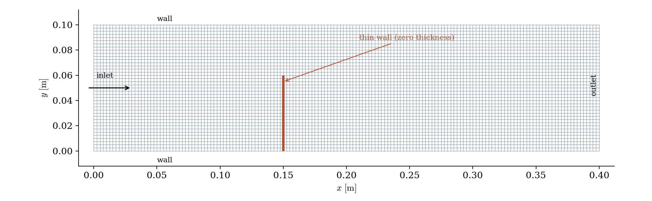
Figure 1: geometry and mesh. The thin wall (orange) lives on existing interior faces: the mesh is untouched, only the connectivity across those faces is cut.
Running the simulation
The commands below start from the tutorial directory:
cd Pre_Thin_Wall/
Run both cases (GUI: open each setup.xml, the thin-wall criteria sits in the Mesh section, then the Run button):
cd CASE_Open
code_saturne run --id open

cd ../CASE_Baffle
code_saturne run --id baffle
Results
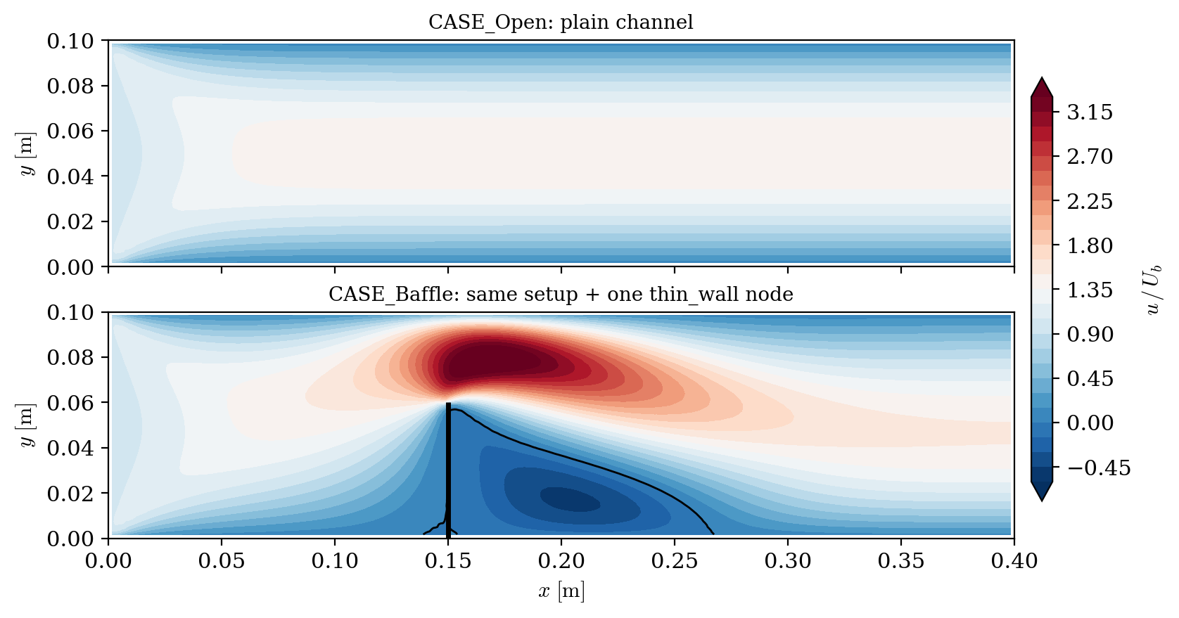
Figure 2: axial velocity (normalized by the inlet velocity). The baffle forces the whole flow through the upper opening, where the velocity reaches about three times the inlet value; a recirculation (zero contour in black) fills the region behind the baffle.
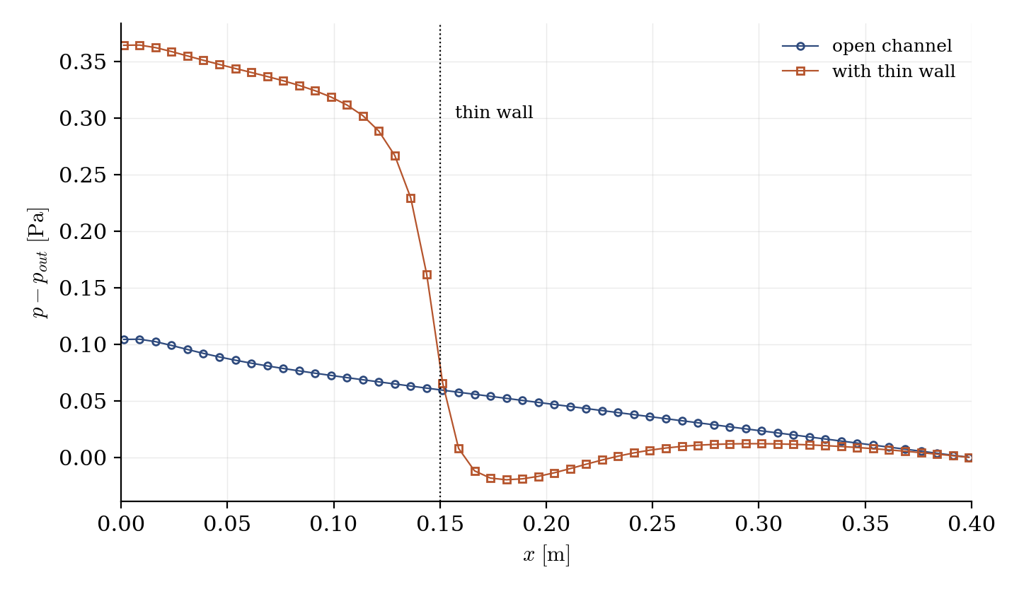
Figure 3: pressure along the channel (at the opening height). The baffle concentrates a pressure drop at the obstacle, roughly tripling the total loss of the open channel.
The checks behave as expected: the flow rate is the same on every cross-section (upstream, through the opening, downstream), the mean velocity in the opening is the inlet value divided by the opening fraction, no flow crosses the baffle, and a recirculation develops behind it over about three opening heights.
Summary
This tutorial inserted a zero-thickness baffle on interior faces from the GUI: one selection criteria in the thin-walls page, plus one wall zone selected by the same geometric criteria, since the created faces carry no group. The mesh itself is untouched: the operation only cuts the connectivity across the selected faces, and the flow responds as it should: blocked at the baffle, squeezed through the opening, recirculating behind, with the added pressure drop concentrated at the obstacle.
References
Authors
Simvia - Questions, remarks and requests are welcome.